 MeshPit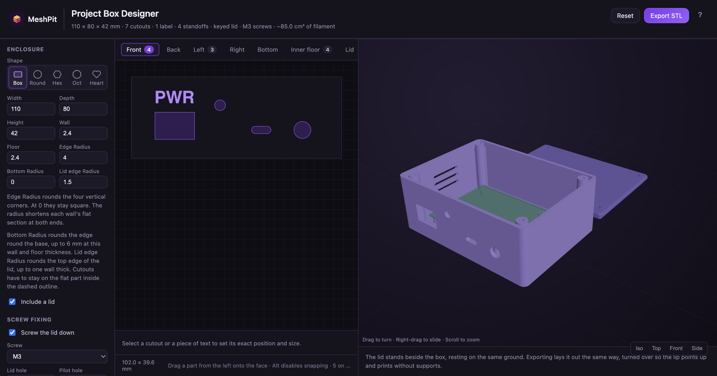
1. Measure what goes inside
Before you open the designer, measure the board and anything else that goes in the box, such as a battery or a relay. Note the tallest part on the board, and which connectors have to reach a wall. Leave a few millimetres of room around the board for cables and your fingers.
If you have the board's mechanical drawing, keep it open. It gives the mounting holes as distances from one corner, and the designer takes them the same way.
2. Sign in and take the tour
Open the Project Box Designer and sign in with your GitHub or Google account. The designer keeps your work in this browser, so a reload doesn't lose it. The ? button in the top right runs a one-minute tour of the screen.
The left panel holds the settings. The middle shows one side of the box at a time, flat, for placing holes. The right shows the box and lid in 3D, with a list of anything that won't print well underneath.
3. Pick a shape and size the box
Under Enclosure, pick a shape. A rectangle suits most electronics, since every wall is flat and takes cutouts. A hexagon or octagon has a flat wall on every side, numbered from Side 1 at the front. A round or heart-shaped box has one curved wall, which the Side view shows unrolled flat.
Then type in the outside size in millimetres. The box starts at 100 × 70 × 40 mm.
| Setting | Default | What it does |
|---|---|---|
| Width, Depth, Height | 100, 70, 40 mm | The outside of the box. The lid sits on top of the walls and adds one wall thickness to the height. A round box has a Diameter instead of Width and Depth. |
| Wall | 2.4 mm | The wall thickness, which is also the lid's thickness. The designer warns below 1.2 mm. |
| Floor | 2.4 mm | The thickness of the bottom. |
| Edge radius | 0 mm | Rounds the four upright corners of a rectangular box. The walls stay flat between them. |
| Bottom and lid edge radius | 0 mm, 0 mm | Rounds the bottom edge and the lid's top edge. The lid edge can't be rounder than the wall is thick. |
To work out the width, add the board's width, the room you want on each side and two walls. Work out the depth the same way. For the height, add the floor, the standoff height, the board with its tallest part, and room above it for wires.
4. Choose how the lid closes
Leave Include a lid ticked for a closed box, or untick it for an open tray.
- A locating lip is a rim under the lid that drops into the box and stops it sliding off. It starts 4 mm deep and 1.2 mm thick, with a 0.25 mm gap on each side so the lid doesn't bind. Raise the Clearance if your printer runs tight.
- Screw the lid down adds a post in each corner. Pick a screw from M2 to M5, and the designer sizes two holes: a clearance hole in the lid the screw drops through, and a smaller pilot hole in the post that the screw cuts its own thread into. For M3 that's 3.4 mm and 2.4 mm.
You can use the lip and the screws together. The screw posts sit inside the lip, so the two don't collide.
5. Mount the board on standoffs
Standoffs are posts on the floor that hold the board up by its mounting holes, with room for solder joints underneath. Open the Inner floor tab, which looks down into the box with the lid off.
Tick Show a board outline and click your board: Raspberry Pi 4 / 3B+, Raspberry Pi Zero, Raspberry Pi Pico, Arduino Uno R3 and BigTreeTech SKR. The designer draws the board and puts a standoff under each mounting hole, sized for the board's screw. Clones don't always match the published drawing, so check each hole against your board.
For another board, type its width and height, then click + Add single standoff for each hole. Set Measure from to the corner your drawing measures from, and type the two distances as the drawing gives them. The standoffs follow the board when you move it. + Configure Board Visually… does the same in a larger window, where you click the board to place its holes.
A standoff starts 5 mm tall, which is the gap under the board. Make it taller if the board has pins or parts on its underside.
6. Add holes for connectors and labels
Pick a side with the tabs above the drawing: Front, Back, Left, Right, Bottom or Lid. Each side is drawn as you'd see it from outside the box. Drag a part from the left panel onto it, or click a part to drop it in the middle.
| Part | Hole |
|---|---|
| USB-C | Panel cutout 9.4 × 3.6 |
| USB-A | Panel cutout 14 × 7 |
| Banana 4 mm | Ø6.2 binding post |
| DC barrel | Ø8.2 — 5.5 × 2.1 jack |
| Rocker switch | KCD11 19.2 × 13.2 |
| Toggle switch | Ø6.2 — MTS-101 |
| Push button | Ø16.2 panel mount |
| LED 5 mm | Ø5.2 |
| M3 clearance | Ø3.4 |
| Vent slot | 24 × 3 rounded |
| Round hole | Ø10, resize to suit |
| Rectangle | 20 × 10, resize to suit |
Every size includes a little clearance, but connectors differ between suppliers, so measure the one you bought. Click a hole to select it, then type its exact size and position under the drawing. Across and Up are measured from the middle of the side. Dragging moves a hole in 0.5 mm steps. Hold Alt while you drag to place it freely.
Click + Add text for a label, such as PWR over a switch. Choose Raised or Stamped in, a font and a size. Text starts at size 8 mm, raised 0.6 mm off the wall.
7. Check the preview and the warnings
Drag the 3D preview to turn the box around and check that every hole is on the side you meant. The lid stands beside the box, turned over when it has a lip, which is how it exports.
Under the preview, the designer lists anything that won't build or print well. For example, it warns when a hole overlaps a screw post, when a board is bigger than the inside of the box, or when stamped text would cut through the wall. Fix every warning before you export.
8. Export and print
Click Export STL and give the file a name. The box and lid come in one STL, side by side on the build plate. Every export is saved under My projects, where you can open it again.
Your first 3 exports are free and have the MeshPit logo raised on the inside floor. After that, an export costs R 18 and has no logo. Each paid export includes 3 free re-exports of the same project, for when the first print needs a tweak. Then, in your slicer:
- Print it as it exports. The box stands on its floor and the lid lies with its lip up, so neither needs supports.
- PLA works for most boxes. Use PETG for a box that sits in a car or in the sun, since PLA softens at about 60 °C.
- Print a test first when a fit matters. A connector that won't go through its hole needs the cutout 0.2 to 0.4 mm bigger.
- When you screw the lid down, drive each screw in slowly the first time so it cuts a clean thread in the post.
Questions
How thick should the walls of a 3D-printed box be?
The Project Box Designer starts at 2.4 mm for the walls and 2.4 mm for the floor, which is stiff enough for a box you pick up and plug cables into. It warns you below 1.2 mm, about two perimeters with a 0.4 mm nozzle, because thinner walls crack.
How much clearance does a 3D-printed lid need?
The designer leaves 0.25 mm on each side between the lid's locating lip and the inside of the walls. Both parts print slightly oversize, so a lid with no gap binds. If your lid is still tight, raise the clearance by 0.1 mm and export again. If it rattles, lower it.
What size hole does a screw need in a 3D print?
A screw that cuts its own thread needs a pilot hole of about 80% of its size, and a hole it passes through needs about 0.4 mm more than its size. For an M3 screw, the designer makes a 2.4 mm pilot hole in the post and a 3.4 mm hole in the lid.
Is the Project Box Designer free?
A free account gets 3 free exports, which have the MeshPit logo raised on the inside floor. After that each export costs R 18 and has no logo, and every export includes 3 free re-exports of the same project. A MeshPit Desktop license (R 299 once) includes the designer with unlimited exports.